

Soon after Menokin’s chimney, we began repairs on an 1870s brick building that had incurred damage from a recent earthquake. This era of construction meant black mortar joints under 1/4″ in diameter and projecting masonry profiles that had endured deferred maintenance.
Most mortar in the decorative projecting bands of masonry had been washed out by rain flooding the skyward-facing joints. Dissimilar metals (anodic cast iron drains downstream of large cathodic copper built-in gutters) contributed to internal drain leader failure. The resulting leaks had caused major deterioration of masonry at the building corners through the foot-thick+ walls.
Had the repointing project occurred two years earlier, the damage the building and tower suffered from the 2011 earthquake would likely not have been so severe. Particularly at the tower, the shaking loosened bricks at the round windows and there was corner cracking as well. Some of this was no doubt increased by the shifting cantilevered balconies above. These windows also span between the cast iron stair landings inside which meant they were moving freely between two hard points inside that were pushing on the building above and below during the earthquake. The metal band holding the polycarbonate “windows” also created a hard point.
Rather than do a typical repair with a series of criss-crossing through-tower ties with ugly pattress plates on the exterior, we decided that carbon fiber buried in the joints would make a more elegant restraint against further outward thrust around these windows. We created a more structural band by folding the epoxy-impregnated carbon fiber tape into a “U” channel, filling the center with epoxy to create a custom built-in-place rigid beam.

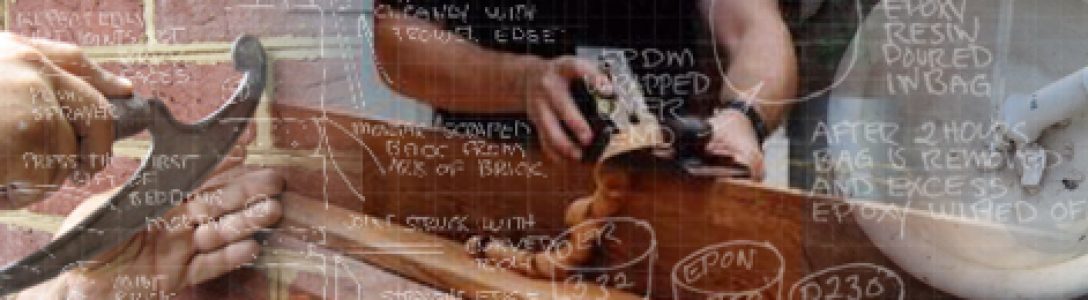
In addition to drawings, it was important to provide the contractor with images from a mockup in the shop that also 1) helped us work out any bugs and 2) to help describe the process to the contractor so they could bid this uncommon repair. We were lucky that although most joints on this building were 1/8″, they were closer to 3/8″ on the tower.

Brushing epoxy on CF 
Spread epoxy evenly 
Various weaves, tapes tested
The bricks on this project were already being masked before pointing due to a 1960s waterproofing that tended to turn white in contact with high pH materials. Because this step eliminated staining of the brick faces, there was essentially no masonry cleaning required, except local brushing with a vinegar/water solution in a few spots. Had masking not already been a part of this project, it certainly should be used on any project where epoxy is being used for a carbon fiber installation to allow for easy cleanup.
Obviously when repointing with lime mortar which is slower to set than portland mortars, it is not an option to hose the entire building down with muriatic acid after the fact because the masonry work was done sloppily. This crew was pretty neat, but with the masking, they could actually afford to be messier with their pointing because the masking would remove any debris and stains. We were very appreciative to have this “Rubber Mask” from American Building Restoration to protect the waterproofed bricks from turning white, but it also took away the cleaning step which is such an integral (and pricey) part of most masonry project budgets. This means we also eliminated the efflorescence risk that comes from leftover acids and the risk of biological growth that plagues so many projects after cleaning due to residual surfactants that become food sources.

Because repairs, including the extent of repointing on this building, were handled on an as-needed basis inch-by-inch, the conservation team determined the areas needing repair and chalked them for the masons. For more information on this project and how the work was laid out by conservators and tracked, see a detailed explanation of how this project was designed and budgeted in advance of eyeballing every joint yet remained under budget in our blog post on Successful Restoration Project Management.
Although the inch-by-inch annotation meant more time on the scaffold for the conservators, it stretched the budget for repairs. In fact when this project started there was no expectation of being able to complete repairs to the tower or the “moats.” Yet because only joints that needed it were repointed, the tower and two most fragile “moats” at 80-ft and 150-ft in length were able to be completed for the same budget that originally was only intended for repairing the main building on the public corner where falling bricks had become a life safety hazard.
In spite of the unique nature of the tower’s carbon fiber stabilization, we had a very agreeable masonry team from Atlantic Refinishing & Restoration that worked with us on this one-off installation. The tape was installed two courses above and two courses below the round windows, wrapping the exterior and then the ends overlapped for a foot before being turned up and locked around a brick above and below into the adjoining courses.


It took many hands to smoothly uncoil the carbon fiber into the joint in an even C shape while not having it snag on the bricks. Building corners were a challenge. They quickly learned how to inject the bedding epoxy, press and fold the CF open into a “U” and keep it open with wood wedges. Superintendent JD Stinner (black shirt) and Masons Mike Manning (white suit) and Mike Barnett were the crew.


In order to impregnate the tape as it went into the joint without wearing the epoxy, a board was hung over the scaffold rail and up to the wall that allowed the tape to be draped across it where epoxy was brushed on and the excess wiped off with a screed right before placing the CF in the joint.

A paint brush handle ensured an even fold and gently pushed the carbon fiber backward without any tearing of the weave.. The U was held open with regularly spaced wedges.
When it came time to inject the epoxy that would fill the “C” to make it rigid, this was a quick and seamless process. We inserted this carbon fiber tension “beam” recessed from the brick faces by 2” so that the front of the joint could be properly pointed afterwards.


When the entire perimeter CF was installed into its C formation at the appropriate depth, the crew came through with tubes of the epoxy to fill the center of the carbon fiber. This was then left to set overnight before the rest of the joint was pointed the next morning.


The rest of the joint was pointed, then the masking peeled off to reveal clean brick
Another last-minute addition to the first phase of this project that became possible due to remaining funds as we neared repointing was repairs — again using carbon fiber — to two of the retaining walls that held back the earth around the basement lightwells which were bowing. (These retaining walls were humorously referred to as “moats.”) These 10′ tall retaining walls were unbuttressed. One was 80-ft in length, the other 150-ft and were just vertically stacked bricks without internal restraint to counteract the thrust of the earth.
Bracing inside the lightwells would have been unattractive and would have restricted egress/access around the building. Likewise, digging out the earth behind and installing proper buttressing was not an option. The 80-ft moat abutted public sidewalks and was integral to electrical substations below the street. Digging behind the 150-ft moat would have required tearing up the childcare playground that daily serviced the children of occupants in a half dozen government institutions. We needed to find a way to resist the thrust of these light well walls from inside the moat that was unobtrusive.
At the sidewalk moat only the top few feet were bowed (above where some earlier bracing had already been installed). Here we opted to relay the top several courses of the wall and reset the cap stones. Carbon fiber was laid into the top few courses with the CF “beam” ends pinned into the return walls to restrict movement.

In the 150’ long moat against the childcare area, we integrated a single continuous course of carbon fiber. This was aligned to bear against the back of star plates set over threaded rod that was driven horizontally under the playground to tie the wall back to a line of concrete deadmen strategically located in a narrow area of the playground so that the holes could be dug, poured, and the padding relaid over a holiday weekend.

You must be logged in to post a comment.